Materials:
- aluminum v-channel
- steel ball
- board
- ring stand with clamp
- carbon paper
- tape
- ruler
- plumb bob
 |
| A complete set up of the apparatus |
Procedure Part 1: Once the apparatus has been set up, we launched the steel ball from an identifiable point on the v-channel to see where it would land. We placed the carbon paper at the impact point on the floor and launched the ball five more times to get a more accurate distance of how far out from the tables edge the ball landed. We hung a plumb bob as well to get even more accuracy. After observing the marks on the carbon paper we used a meter stick to measure the distance from the edge of the table to the impact point.
The measured horizontal distance was 0.734 meters. We were asked to determine the launch speed of the ball, so we needed the vertical height as well, which was 0.874 meters.
Using kinematics in two dimensions, we calculated the time the ball was in the air using the vertical height and gravity. Once we had the time, we were able to determine the speed.

The time in the air is for both x and y components, but the initial velocity is only in the x direction.
Procedure Part 2: After calculating the launch speed, we had to imagine attaching an inclined board at the edge of the table and when launched from the same position, the ball will strike the board a distance d along the board.
The horizontal distance was 0.835 meters and the vertical distance was the same as in part 1.
We measured the angle α to be 46.3º using tan^-1(y/x)
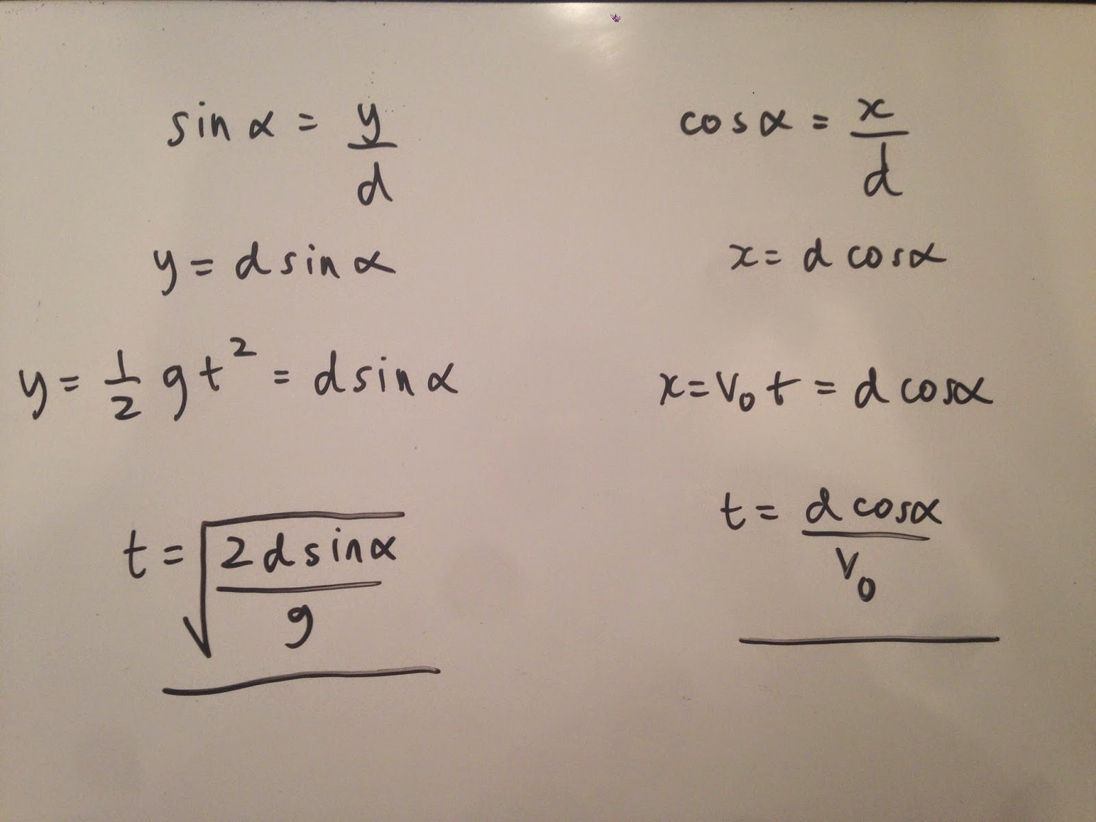
Given that we know the values of v0 and α, we derived an expression that would allow us to determine d along the board.

Our experimental value of d was 0.947 meters.
Once we determined d we set up the apparatus again, but with the board held in place by a weight and tape.
We then placed the carbon paper along the board a distance d, based on our experimental value and launched the ball five more times from the same initial point as in part 1.
The mark inside the red square is the impact point along the board. We next calculated the uncertainty in our experimental value of d.
In our derived equation for d, we needed an expression for v0 that represented a function of x and y. we started with the equation v=x/t and used the x and y components of the projectile to create an expression for v0 that we could plug into our propagated uncertainty formula.
Above is the experimental calculations for d.
Conclusion:
The equation used in calculating percent error
Our calculations showed that d = 0.936 m +/- 0.125 m. Our measured theoretical value was 0.890m. This yields a % error of 5.17%, which shows our experimental value compared well to our theoretical value. Possible sources of error could have been accidental moving of the board or v-channel. The v-channel was constantly being readjusted due to slipping. We could have easily avoided this by using tape.


No comments:
Post a Comment